|
Prusa MINI Firmware overview
|
The main goals set at the initiation of this document was to reach the following targets:
Prusa 32 Bit Firmware architecture is based on the historical experience with previous printers and general requirements for the new Prusa Printers firmware as follows:
The most of the above requirements are covered by STM CUBE firmware, which will be explained further.
The general requirements lead to the below architecture layers:
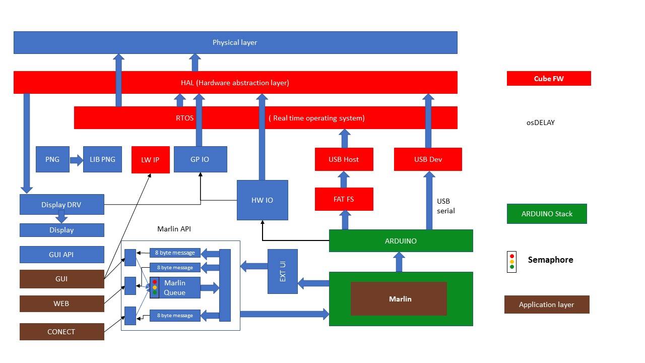
Picture 1. 32 bit Firmware architecture
Main purpose of the physical layer is the peripherals, processor registries and ports management on the physical layer, interfacing with stepper motor drivers etc.
Hardware Abstraction Layer contains a set of functions unifying the hardware for the programmers, where the use of logical naming conventions is implemented instead of using physical registry numbers and PIN numbers which could be different for different HW variations.
Basic function of the HAL is to configure and set up an initial configuration peripherals or registers. It will receive a specific structure and parameters which will be transferred to corresponding registers. For each part of the physical layer within HAL there is a separate function (e.g. for interrupt handling, timer manipulation, GPIs) available for programmers. Each function name consists of a HAL prefix plus and abbreviation pointing logically to the set of functions like SPI, USB, UART, I2C, etc. HAL is internally sometimes more complicated, so it has to be used carefully. HAL is written in simply C. HALL has to be always used by Arduino layer (like middleware) when approaching GIO resources. In case of a HW change only HAL code has to be redesigned. Internal structure of the HAL should be obviously hidden for the functional programmers. HAL is initially configured by STM CUBEXM (see below).
The main purpose of RTOS used in Prusa 32 Bit Firmware is to provide multithreading/multitasking functionality. Several parallel tasks running in multitasking mode will simplify programming work and reduce complexity in HW as well as at SW interrupt handling. The main purpose for RTOS is to start parallel tasks/threads, synchronise between tasks and manage the use of shared resources - namely queues.
Multithreading also simplify the programming, where several functions can be seen as independent and can be developed in parallel. Multitasking will be handled by the OS kernel functions. All three applications from application (see picture 1.) layer and Marlin are running as separate tasks/threads.
RTOS also takes care of the Marlin API queue handling, where three applications share the same entry queue of Marlin API. It is served via RTOS semaphores (see below). FREE RTOS TM has been selected for Prusa 32 bit Firmware. The main reasons are OPEN-SOURCE and existing porting on the selected STM Microcontroller. The important part of the Free RTOS is a CMSIS RTOS module, which facilitates Semaphores, Mutexes Queues etc. Apart of the tasks synchronisation and queue handling, the use of the RTOS within the application APIs is limited.
USB Device is basically a CDC port. On the ARDUINO level it behaves like USB serial – read/write class. Disadvantage of the CDC port is a missing possibility to Debug.
Provides USB device connection for Flash disk through USB plug.
FAT Filesystem supports FAT and exFAT structures.
The purpose of the ARDUINO layer is to host the Marlin API. The Arduino functionality has been significantly reduced and parts, they needed to be kept, were rewritten internally. ARDUINO also emulates SD cards for Marlin via specific Marlin classes.
HW IO is a library with main role to provide an interface between ARDUINO layer and Hardware components. HW IO filters and redirects Marlin´s access toward GPIO. Marlin is interfacing toward ARDUINO layer and ARDUINO further communicates with HW IO. The main purpose is to let CUBE Firmware execute initial ports, registers and other peripherals configuration and not to be interfered by MARLIN, who has it´s own initial peripheral configuration implemented as well. Marlin is only allowed to use the configured resources at the later phases. Standard ARDUINO read/write functions are also rerouted via HW IO.
GP IO significantly simplifies access to GPIO routines providing PIN mappings from logical to HW naming.
Display driver type is the ST 7789V, 320x240 hi core resolution. The application does not use a frame buffer (large RAM memory consumption), so information on the display is rendered dynamically. In order to minimize the amount of resources needed for information presentation the display driver has only limited set of functions. It is used to draw pictures and a limited set of functions are used for basic geometry drawing - like lines, characters or dots. The purpose of this library is to simplify the transition to another type of display in case of HW change. With arrival of a new display only the Display library is to be redesigned. The display driver utilizes the SPI communication.
After several considerations and evaluations PNG image format has been selected for PRUSA 32 Bit Firmware. PNG format contains Alpha channel, which allows a simple and comfortable image manipulation with use of limited resources. PNG compression level 15 is used. PNG layer and LIB PNG are handling the display output.
GUI API is comparable with WIN API for WIN GDI. It it manipuates with windows, screens, screen classes. GUI API is written in C language.
Serves all generic GUI functions and communicates with Marlin via Marlin API.
Marlin version 2. is used for interpretation of G-codes and managing prints as well as other functions (movement, heating, extrusion, etc). Development team has a goal to keep Marlin as much as possible without any modifications.
Marlin API facilitates the communication between several FW applications (separate threads) like GUI, WEB, CONNECT and Marlin. Communication of the applications toward Marlin is executed via semaphored (circular) queue access in order to manage data synchronisation and data access granting.
Most of the requests toward Marlin are character types, so the queue type is also character. Marlin is interpreting text codes (G-codes) with maximum length of 96 characters – usually one G-code line. Marlin API buffer should accommodate two requests in fact, that Marlin cannot wait for next request. Typically, the application sends a request to Marlin queue to set the semaphore, after the semaphore acknowledgment is received, application stores data in the queue and releases the semaphore for further use.
The important requirement regarding the massages is a non- blocking request in order not to block Marlin. After the message is picked up from the queue Marlin calls the appropriate routine to execute. There are some situations where the G-Code processing blocks the main loop. In those cases we have to be aware about it and take appropriate measures. In the future adjustments shall be made in order to eliminate those blockings.
Important note: Marlin is running as one of the separate tasks in parallel with other tasks in multitasking environment. Therefore any communication between other tasks and Marlin must be strictly executed via Marlin API interface in order to keep data consistency and synchronisation.
For the reversal communication with other applications Marlin has an interface called EXT UI. Each client (application) owns its own message buffer - queue which is filled in by Marlin and picked up and processed by particular application. Marlin generates events and/or status changes (like temperature change, coordinates change etc.) which can be presented to end users. Each application receives an updated information about changes. In case the application requires an information immediately, it sends the request for refresh, which is acknowledged and executed by Marlin immediately. The refresh frequency is 100 milliseconds.
The Marlin´s communication toward applications is not strictly character based. The maximum required information length is 4 bytes. Marlin communicates toward applications via buffered queues using self-explanation 8 bytes long variant types. First byte represents the type, next tree bytes are user defined parameters and last four bytes represent data.
All variables, their content have to be sent toward application, have a change flag, so in case the information has not been entered to the queue (due to full queue), it is sent within next attempt. In the worst case the end user will not receive all changes in the shortest time.
EXT UI is a Marlin outgoing interface. It can be characterized by a set of Callbacks notifying, that there is a change inside Marlin.
LW IP API consists of DHCP server, complete internet stack, and UDP server.
CUBE FW is one of the strongest features of STM embedded RTOS and is used for initial configuration of the whole RTOS, HAL and Peripherals (see picture 1.) via graphical CUBEMX feature of STM32CubeIDE application. The outcome is the code generated in C language for several items of the FREE RTOS.
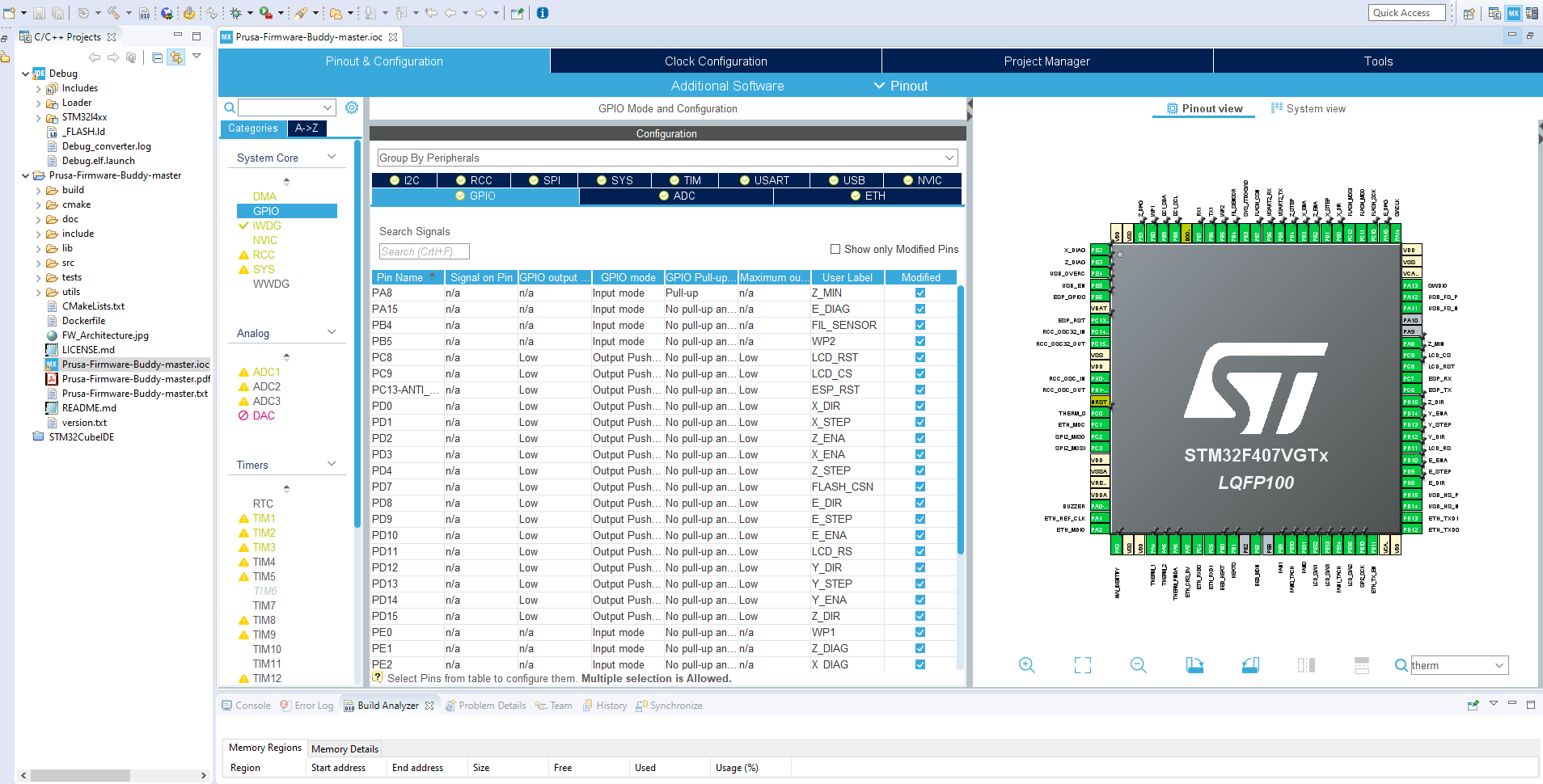
Picture 2. STM32CubeIDE application overview screen
For the implementation for the 32-Bit Firmware solution a CMSIS RTOS real time multithread/multitasking OS has been chosen for several reasons:
Heap management can use several methods of RAM allocation during objects linking or dynamic RAM allocation at runtime. Below we describe the Heap 4 which was selected for Prusa 32-bit Firmware.
Heap 4 works by subdividing an array into smaller blocks. As before, the array is statically declared, and dimensioned by configTOTAL_HEAP_SIZE, so will make the application appear to consume a lot of RAM, even before any memory has actually been allocated from the array. Heap 4 uses a first fit algorithm to allocate memory. Heap 4 combines (coalescences) adjacent free blocks of memory into a single larger block, which minimizes the risk of memory fragmentation. Heap 4 combines (coalescences) adjacent free blocks into a single larger block, minimizing the risk of fragmentation, and making it suitable for applications that repeatedly allocate and free different sized blocks of RAM. Heap_4 is not deterministic, but is faster than most standard library implementations of malloc() and free(). When FreeRTOS requires RAM, instead of calling malloc(), it calls pvPortMalloc(). When RAM is being freed, instead of calling free(), the kernel calls vPortFree(). pvPortMalloc() has the same prototype as the standard C library malloc() function, and vPortFree() has the same prototype as the standard C library free() function. pvPortMalloc() and vPortFree() are public functions, so can also be called from application code. The first fit algorithm ensures pvPortMalloc() uses the first free block of memory that is large enough to hold the number of bytes requested. For detailed Heap management and RAM allocation methods see Reference (1) Chapter 2, Heap Memory Management
Prusa 32 bit Firmware is using Prioritized Pre-emptive Scheduling with Time Slicing. Pre-emptive scheduling respects the priority assigned to task and prefers higher priority task against the one with lower priority.
Tasks are implemented as C functions. The only thing special about them is their prototype, which must return void and take a void pointer parameter. Each task is a small program on its own. It has an entry point, will normally run forever within an infinite loop, and will not exit. FreeRTOS tasks must not be allowed to return from their implementing function in any way—they must not contain a ‘return’ statement and must not be allowed to execute past the end of the function. If a task is no longer required, it should instead be explicitly deleted. A single task function definition can be used to create any number of tasks—each created task being a separate execution instance, with its own stack and its own copy of any automatic (stack) variables defined within the task itself. Detailed description in (1) and (2). As usual the central starting point is the main() loop, which starts at the beginning and configures all parameters and peripherals including the threads/tasks. Tha last called function of the main() function is the osKernelStart()- which in reality starts the RTOS scheduler in indefinite loop.
There must always be at least one task that can enter the Running state (See Reference 1). To ensure this is the case, an Idle task is automatically created by the scheduler when vTaskStartScheduler() is called. The idle task does very little more than sit in a loop—so, it is always able to run. The idle task has the lowest possible priority (priority zero), to ensure it never prevents a higher priority application task from entering the Running state.
DefaultTask is the main task/thread running the Marlin routines, executing all functions regarding printing and controlling printer statuses and peripherals like stepper() motor and temperature() control. The Marlin functionaity is represented by app_run() function and is initiated by StartDefaultTask() function.
GUI is running in the next thread called DisplayTask. GUI is processing all user input/output functions. It controls the display and handles the input from the Jogwheel. DisplayTask communicates with Marling via already mentioned Marlin API interface calling the _send_request_to_server() function which is entering the data to the marlin_queue() and which uses the Marlin osSemaphoreWait() and osSemaphoreRelease() functions for granting access to marlin_queue(). The functionality is provided by gui_run() function and the thread initiation is executed via StartDisplayTask() function within the main() loop.
Webtask is a next thread of the multitasking operating system. It provides a connection for the user via web API configured as web server. The main purpose is the remote end user connection. For scheduler it is known as WebServertask.The thread initiation is executed via StartWebServerTask() function.
MeasurementTask is a brand new task in the system and deals with the all functionality regarding the (for MINI optional) Fillament detection sensor of Original Prusa MINI printer and it´s successors based on STM32F4XX microcontrollers. It is represented by fs_cycle() function and initated within main() loop via StartMeasurementTask() function.
Connect is the future function. It´s task is to connect the printer to the management network in role of the slave. The typical network is represented by printer farm or similar type of the network. This function is not implemented yet.
The marlin_server_queue() is the main part of the Marlin API hadled via marlin_server_sema() semaphore. The queue and the semaphore both are started and initiated within the marlin_server_init() function. Marlin semaphore is approached via function call _send_request_to_server()
As it has been mentioned in chapter 2.14.2, Marlin communicates towards other tasks via marlin_client_queue(). The number of client queues is determined by the number of tasks they are registered to send a message to Marlin. This is represented by MARLIN_MAX_CLIENTS constant. For the current configuration MARLIN_MAX_CLIENTS=2. The communication from clients (applications) towards Marlin are executed via separated queues. For this reason there is no need to use a semaphores for exclusive access to resources.
The STM32F407xx device includes
They can be configured in several ways,co-operate with Timers, referenced to ADC and assigned to GIO PINS as well.
Prusa MINI uses 7 Timers in the following configuration :
TIM1 - hwio - FAN0 and FAN1 PWM
TIM2 - hwio - BUZZER
TIM3 - hwio - HEAT0 and BED_HEAT PWM
TIM4 - not used
TIM5 - Marlin/Stepper
TIM6 - System timer, ADC
TIM7 - Marlin/Temperature
TIM8 - not used
TIM9 - not used
TIM10 - not used
TIM11 - not used
TIM12 - not used
TIM13 - not used
TIM14 - GUI - jogwheel, hwio
The previous table can be divided into two generic parts:
The first group consist of Timers, which are configured and initiated via CUBE IDE tool. These are TIM1, TIM2,TIM3 and TIM14.
TIM1 generates PWM signals via its PWM Channel1 for FAN1 (Print fan) on the processor PIN PE11 and PWM Channel2 for FAN0 (Nozzle FAN) on the PIN PE9.
TIM2 Generates PWM signals via it´s Channel 1 for BUZZER on PIN PA0-WKUP.
TIM3 generates PWM signals via its PWM Channel3 for Heat Bed on the processor PIN PB0 and PWM Channel4 for HEAT0 (Nozzle ) on the PIN PB1.
TIM6 is a system timer whose role is to control sampling of analog IO pins assigned for A/D convertors. Interrupt activates the ADC assigned pins reading of PA4 (THERM_1), PA5 (THERM_2), PA6 (PINDA) and PC0 (THERM0 - HeatBed) connected with termistors. Measured values are stored in buffer for further use by Marlin.
TIM14 is a global interrupt used for scanning input signals from jogwheel encoder on PINS LCD_SW1 (PE12), LCD_SW2 (PE13) and LCD_SW3 (PE15)
After code generation run from CUBE IDE several source files with generated code are ready for use. Among them you can find files with starting prefix stm32f407xx in subdirectory \lib\Drivers\STM32F4xx_HAL_Driver\Inc
The second generic group consists of Timers TIM5 and TIM7, which are initiated and used by Marlin (see Figure 1.) embedded into the code of Marlin. Their role is to control Marlin Stepper Motors (TIM5) and in Marlin Temperature control (TIM7). TIM7 generates 1kHz frequency interrupts and calls Marlin.
In order to ensure sufficient accuracy Marlin Stepper utilizes interrupts with frequency tens of KHz, while TIM7 can work with lower interrupt frequency arround 1kHz.
| Component | Action | Timer | Channel | PIN | Frequency |
| Hotend Fan | PWM Spin | TIM1 | CH1 | PE9 | |
| Print Fan | PWM Spin | TIM1 | CH2 | PE11 | |
| Buzzer | PWM Sound | TIM2 | CH1 | PA0 | |
| Nozzle | PWM Heat | TIM3 | CH4 | PB1 | |
| Heatbed | PWM Heat | TIM3 | CH3 | PB0 | |
| Marlin stepper | Print Step | TIM5 | - | PC0 | |
| Heatbed Temp | ADC Scan | TIM6 | - | PC0 | |
| Nozzle Temp | ADC Scan | TIM6 | - | PA4 | |
| Ambient Temp | ADC Scan | TIM6 | - | PA5 | |
| PINDA Temp | ADC Scan | TIM6 | - | PA6 | |
| Marlin TEMP | PID control | TIM7 | - | - | |
| Jogwheel | D Scan | TIM14 | - | PE12 | |
| Jogwheel | D Scan | TIM14 | - | PE13 | |
| Jogwheel | D Scan | TIM14 | - | PE15 |
The below picture shows the STM32F407VGT pinout for Original Prusa MINI printer configured with help of STM32CubeIDE platform.
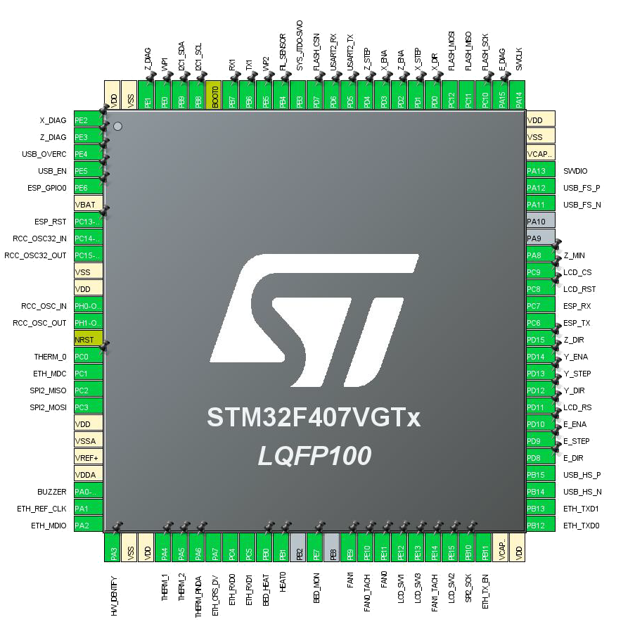
Picture 3. STM32F407VGT microcontroller pinout
(1) Mastering the FreeRTOS Real Time Kernel-A Hands-On Tutorial_Guide.pdf
(2) Developing applications on STM32Cube with RTOS.pdf
(3) FreeRTOS_Reference_Manual_V10.0.0.pdf
(4) STM32CubeIDE platform official site
(1) Prusa-Firmware-Buddy-master.pdf configuration report generated from STM32CubeIDE.
| FREE RTOS | real time operating system |
| CMSIS<td >Cortex Microcontroller Software Interface Standard | |
| ISR | Interrupt Service Routines |
| NVIC<td >Nested vector interrupt control |
 1.8.16
